Go to...  | Start A New Topic  | Search  | Notify  | Tools  | Reply To This Topic  |  |
 6/12 6/12Formally known as "Humbojb"  |
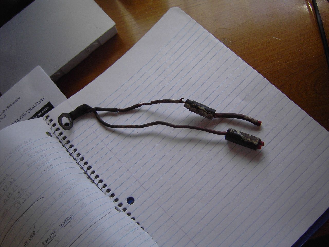
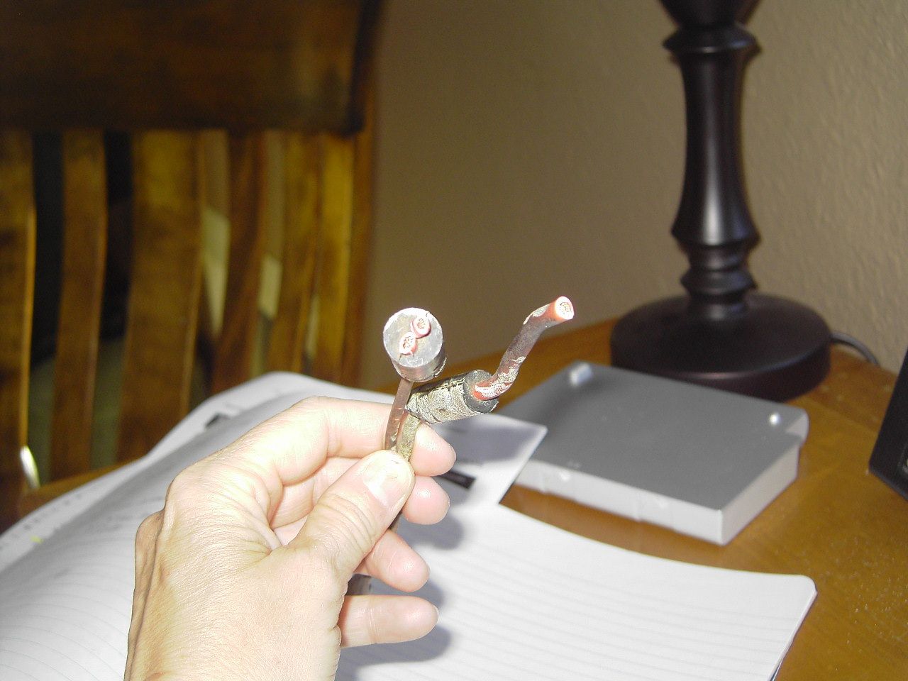
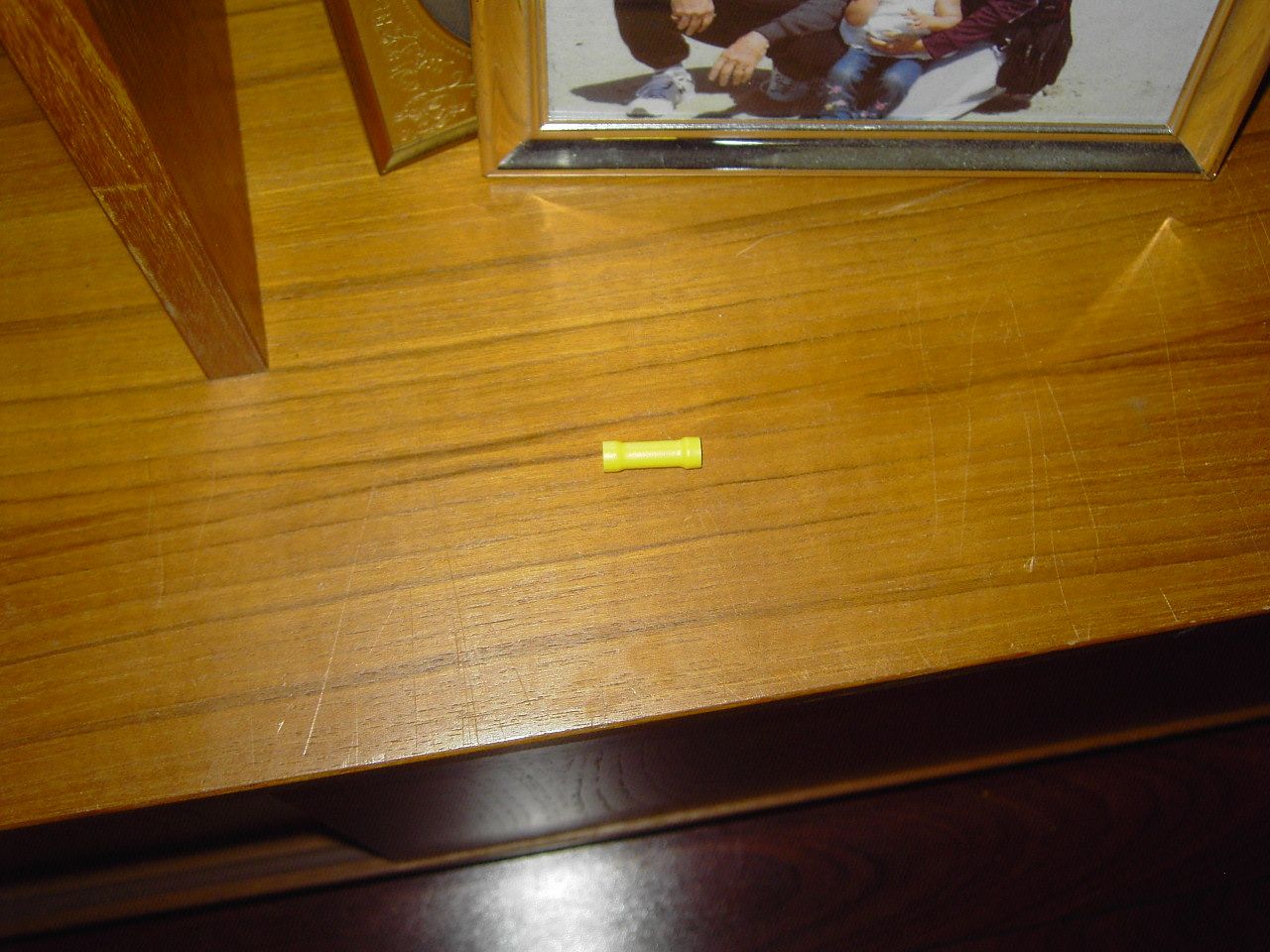
   Pictures are of our wire condition @ starter, splicing technique very substantial(not by us), yellow 10g wire butt connector on hand The location of these wires was @ the starter going up to the non grounding, 4 terminal, intermittent duty, electromagnetic relay & other places I have yet to discover. We replaced our old clunky starter with a new smaller gear reduction permanent magnet starter & therefore were able to assess the wiring at the starter. We found this splice technique used. My questions are 1)What kind of connector is this? It is obviously something I don't have at my local auto suppliers. 2)Is it ok to use the 10g yellow connector to manage my splice until I am able to attack replacing the wiring at a later date? a-later date means maybe a year & a few thousand miles from now FYI This is the only place where the wiring was bad. I would use heat shrink wrap just to protect dirt etc from entering the connectors & I am covering the entire set of wiring with a 1800*degree heat shield webbing that slides over all these connections. & there will be a new starter heat shield blanket, starter heat shield, & new header blanket to protect these wires. We hope to put the header heat shield discussed in previous docs after I get more info back on gauge of steel used & the issue of the template not fitting well in our application due to some immovable tubes by me. So this may not happen any time soon. Thanks, Tere
| |||||||||||
|
| The Old Man and No Barth |
I've had long-term success using butt connectors, though you should use a professional crimping tool, and be certain the connection is tight, by tugging on the wires after you've crimped them. You can get away with using 12 ga. wires in a 10 ga. connector by doubling the stripped wire & folding it over so it makes a snug fit in the connector. A dab of silicone in the connector ends, after the splice is completed, will keep water out for a long time. In the example you've shown here, I'd replace the ring connector & the short leads w/12ga. wire, use a 12 ga. connector on the single lead, & the 10 ga. connector on the double lead, with the stripped end of the single short 12 ga. lead doubled to make a snug fit in the larger connector. By all means, scrape the corroded ends on the old wires to make them reasonably shiny, & twist all the stripped ends before you plug them into the connectors. El Segundo Bill, & some of the others here would advise you to make twisted, soldered connections, & insulate them with heat shrink tubing, but they're pros used to working in professional facilities. When you're working under a shade tree, you use the easiest solution available. I can't think of an easier way than this one, & it works. I can't make out exactly what it is you're holding in your hand, but if it is a simple splice, & you can find butt connectors large enough to accommodate the wires, it should work equally well. | |||
|
 6/12 6/12Formally known as "Humbojb"  |
Our question is this: The spices look like rubber was poured into a mold around the spliced joint, allowed to cool, and then the mold removed. These splices are unlike anything I've ever seen. There's no way of telling if GM did it, Barth, or some repair guy over the last 20 years. You can't pull it apart, water can't get in it. It looks great. I've had but joint splices fail just sitting there, but, not being very skilled, it was probably my fault. I'm like Mike Holmes (Holmes on Homes), DO IT RIGHT THE FIRST TIME. Problem is I don't know what 'right' is. Jim
| ||||||||||||
|
| First Month Member |
I would use a butt splice located farther up away from the heat. Their insulation doesn't take heat well. I would seal each end with liquid electrical tape or Shoe Goo. (Goop same thing). Slip some Thermo Tec tubing over the whole thing, then put a heat shield on the headers near the starter. I believe the Thorleys came with one or two. Just make a copy of one if you have one. If not, holler. . 84 30T PeeThirty-Something, 502 powered | |||
|
 6/12 6/12Formally known as "Humbojb"  |
Well, Dan, the famous jet pilot, aka son-in-law, returned home tonight, took one look and said that what I have is two fusable links. We'll have to get new ones and splice them in. Bill, my Thorley headers have NO heat shields. Guess it's time to call Thorley. All the wires from the starter 24" toward the battery, and all the wires from the starter about 30" toward the front of the engine are cooked. What a job Jim
| ||||||||||||
|
 6/12 6/12Formally known as "Humbojb"  |
Three wires coming off the starter have fusible links. They all appear to be 10 gage. In researching fusible links, they have different temperature ratings. Does anybody have an idea of what type of fusible link I have on this 85 Regal?
| ||||||||||||
|
 8/11 8/11 |
You can purchase fusible link from any "real" auto parts store. Billy & Helen Thibodeaux Retired from Billy Thibodeaux's Premiere RV, Inc. Scott, LA 70583 I-10 Exit 97 The Farm is near Duson, LA I-10 Exit 92 then N 1 mile on right Three Full 50 Amp RV Hookups ! billynhelen@me.com Data Tag: 9404-3908-36XI-2C 1994 Sovereign 36' Widebody on Spartan IC (Mountain Master Lite) Chassis. Powered by Cummins ISL9-450 Onan 8,000 Quiet Diesel Genset Toad: 2018 Chevy Colorado ZR2 Diesel with M&G Car Brake  | |||
|
| The Old Man and No Barth |
If those fusible links are in the engine's electrical system, take them to your local parts store, tell them what engine they come from, & where they are installed. Any parts guy worth his salt should be able to find them in his catalogs & match them up with what you need. | |||
|
 6/12 6/12Formally known as "Humbojb"  |
Well, here in east Tennessee, I guess we don't have any auto parts store. These things haven't been used in 20 years and the current breed of auto parts guys in this area don't know what to sell me. Fusible links are rated by amperage and these could be anywhere from 8amps to 120 amps. I even called the local Chevvy truck dealership and no one could tell me anything other that they haven't seen or delt with these for years. And their parts list aren't of any help since they don't go back that far and even if they did, the part numbers don't tell you amperage. I have electrical drawings but again they don't say amperage. This thing is really p***ing me off. I'm about to have a fire sale.
| ||||||||||||
|
| First Month Member |
What gauge wire is the fusible link protecting? Mine is a metric 5, which is about a 10 AWG. A fusible link is just a way of protecting wires from overloading. Better to burn up something you understand and can find than anywhere than to burn up a hidden wire. From there, we can work through an ampacity chart to select the right size fuse or replacement link. I don't like fusible links, and always replace them with a Maxi or an AGU fuse. My preference is an AGU in an inline hodler, as it is easier to splash-proof than a Maxi inline holder. Let me know if you wanna go that way and I'll get going on it with some numbers and sources. I have them somewhere. However, you can go quick and dirty and simply replace the fusible link with a smaller gauge wire, and it will burn open if it is overloaded, just like a fusible link. Or a fuse, for that matter. . 84 30T PeeThirty-Something, 502 powered | |||
|
 3/11 3/11 |
See: http://www.repairconnector.com...-Gauge-With-Tab.html 1993 32' Regency Wide Body, 4 speed Allison Trans, Front Entry door, Diamond Plate aluminum roof & 1981 Euro 22' w Chevy 350 engine and TH 400 tranny | |||
|
| Powered by Social Strata |
| Please Wait. Your request is being processed... |
|
This website is dedicated to the Barth Custom Coach, their owners and those who admire this American made, quality crafted, motor coach.
We are committed to the history, preservation and restoration of the Barth Custom Coach.
We are committed to the history, preservation and restoration of the Barth Custom Coach.


